The core components of the product achieve 100% domestic production, ensuring supply chain stability and high-quality reliability.
Utilizing high-precision magnetic induction technology, we provide single-turn and multi-turn encoder solutions.
Supports parallel push-pull output with selectable Gray code or binary code to meet diverse control interface requirements.
Features exceptional impact and vibration resistance, with an IP68 rating for maximum protection, making it suitable for extreme industrial environments.
Built-in reverse short-circuit and short-circuit protection effectively minimizes the impact of installation errors on the encoder.

Product Specifications (Parallel Push-Pull Signal Output Series)
| Parameter Name | SAS/M58A (Solid Shaft) | SAS/M58C (Blind Hole Type) |
|---|---|---|
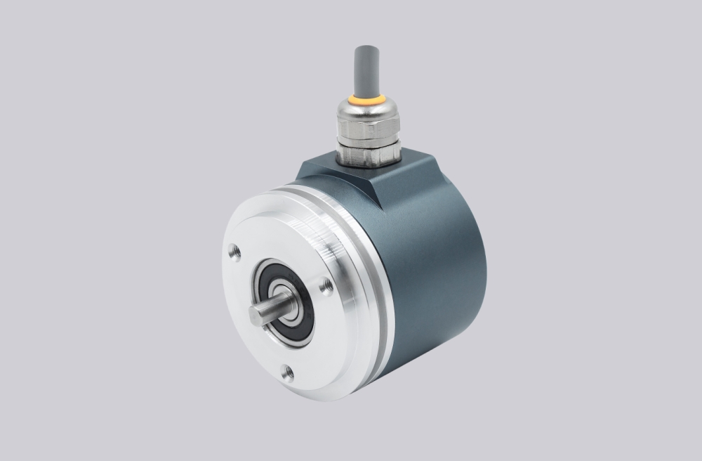
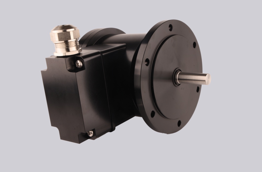
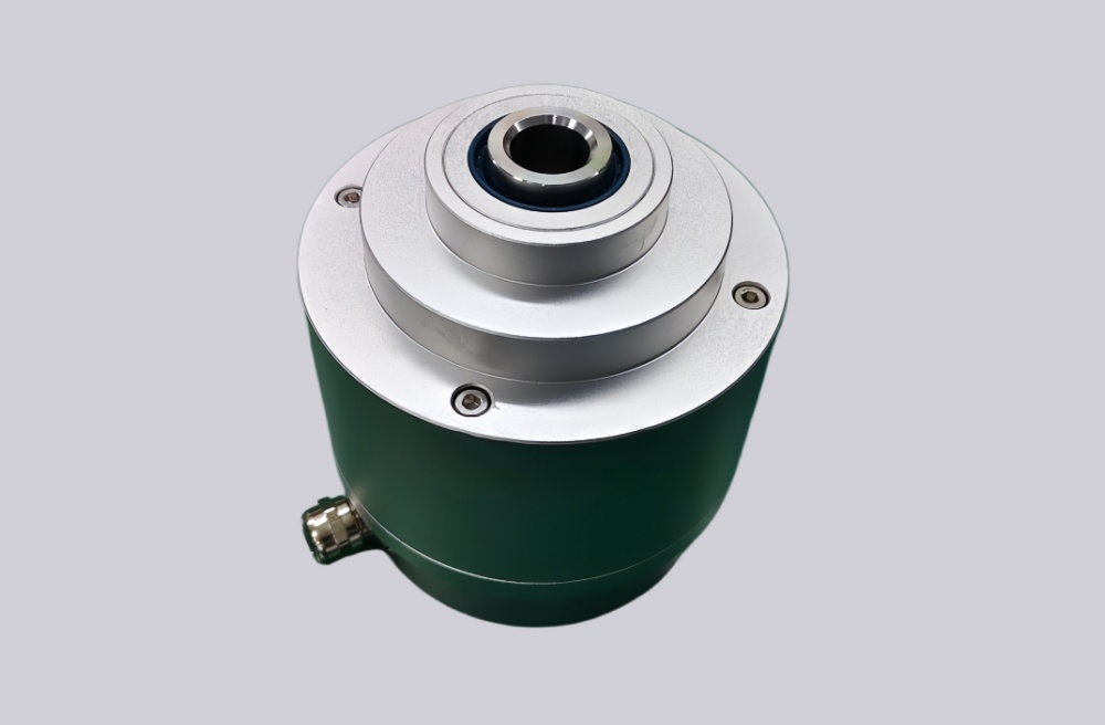
| Functional Features | Ø 58mm solid shaft | Ø 58mm blind hole type |
| Spindle Dimensions | Ø 6, 8, 10, 12, 15 mm (Other sizes available upon request) | |
| Housing Material | Aluminum (optional stainless steel housing) | |
| Signal Output Interface | Parallel Push-Pull | |
| Output Driver | Push-pull | |
| Function | Single-turn or multi-turn | |
| Power supply voltage | 10 to 30 VDC | |
| Single-turn resolution | Standard values are 12 bits (4096), 13 bits (8192), and 16 bits (65536). | |
| Number of laps | 1 revolution (single-revolution type), multi-revolution standard 12 digits 4096 revolutions, multi-revolution maximum selectable 14 digits 16384 revolutions | |
| Physical Properties | Maximum speed: 6000 rpm | Spindle load: Radial 200N, Axial 100N |
| Environmental Indicators | Protection rating: IP65 or IP68; Starting torque: < 0.01Nm | |
| Connection Method | 4×2×0.2-8-core shielded cable, M12-5-core, M12-8-core, M23-12-core male flange connectors | |
| Qualification method | Radial side outlet, axial rear outlet | |
Wiring Definitions
| Single-turn encoder | |||
|---|---|---|---|
| Wire color | Binary code | Gray code | Explanation |
| 棕 | Vcc | Vcc | Power cord |
| 白 | 0V | 0V | |
| 黑 | P-set | P-set | Functional Line |
| 蓝 | DIR | DIR | |
| 灰 | LATCH/2¹⁵ | LATCH/G₁₅ | |
| 粉 | 2⁰ | G₀ | Data cable |
| 紫 | 2¹ | G₁ | |
| 红 | 2²^2$ | G₂ | |
| 橙 | 2³ | G₃ | |
| Light blue | 2⁴ | G₄ | |
| pale green | 2⁵ | G₅ | |
| White and Blue | 2⁶ | G₆ | |
| White and green | 2⁷ | G7 | |
| White and yellow | 2⁸ | G₈ | |
| White Orange | 2⁹ | G₉ | |
| White Palm | 2¹⁰ | G₁₀ | |
| White and Red | 2¹¹ | G₁₁ | |
| Black and white | 2¹² | G₁₂ | |
| 绿 | 2¹³ | G₁₃ | |
| 黄 | 2¹⁴ | G₁₄ | |
| Multi-turn encoder | |||
|---|---|---|---|
| Wire color | Binary code | Gray code | Explanation |
| 棕 | Vcc | Vcc | Power cord |
| 白 | 0V | 0V | |
| 黑 | P-set | P-set | Functional Line |
| 蓝 | DIR | DIR | |
| 灰 | LATCH/2²⁷ | LATCH/2²⁷ | |
| 粉 | 2⁰ | <td2⁰Data cable | |
| 紫 | 2¹ | 2¹ | |
| 红 | 2² | 2² | |
| 橙 | 2³ | 2³ | |
| Light blue | 2⁴ | 2⁴ | |
| pale green | 2⁵ | 2⁵ | |
| White and Blue | 2⁶ | 2⁶ | |
| White and green | 2⁷ | 2⁷ | |
| White and yellow | 2⁸ | 2⁸ | |
| White Orange | 2⁹ | 2⁹ | |
| White Palm | 2¹⁰ | 2¹⁰ | |
| White and Red | 2¹¹ | 2¹¹ | |
| Black and white | 2¹² | 2¹² | |
| White and purple | 2¹³ | 2¹³ | |
| White lime | 2¹⁴ | 2¹⁴ | |
| Yellow and Blue | 2¹⁵ | 2¹⁵ | |
| Yellowish gray | 2¹⁶ | 2¹⁶ | |
| Yellow-orange | 2¹⁷ | 2¹⁷ | |
| Yellow and red | 2¹⁸ | 2¹⁸ | |
| Yellow and purple | 2¹⁹ | 2¹⁹ | |
| pink and black | 2²⁰ | 2²⁰ | |
| pale yellow | 2²¹ | 2²¹ | |
| pinkish orange | 2²² | 2²² | |
| pinkish green | 2²³ | 2²³ | |
| Pinkish brown | 2²⁴ | 2²⁴ | |
| Yellow and black | 2²⁵ | 2²⁵ | |
| Yellow-brown | 2²⁶ | 2²⁶ | |
1) P-set External Set Line:Single-turn zero-point positioning: When in contact with VCC, the current position data output represents the zero-point position of the entire data set; (The above is the factory default setting for this parameter, but customization is available: Single-turn midpoint positioning requires specification prior to ordering). Multi-turn center positioning: When briefly contacting VCC, the current position data output represents the zero-point position of the entire data range; (The above is the factory default parameter. Customization is also available: Multi-turn center positioning requires specification prior to ordering).
2) LATCH Data Latching:Connect to 0V or leave unconnected (real-time output of position data); Connect to VCC (latch this value);
3) DIR Count Direction Line:When connected to VCC (facing the shaft, data increases counterclockwise); when connected to 0V (data increases clockwise).
4) Shield:Cable outlet.
Installation Dimension Drawing
SAS/M58A
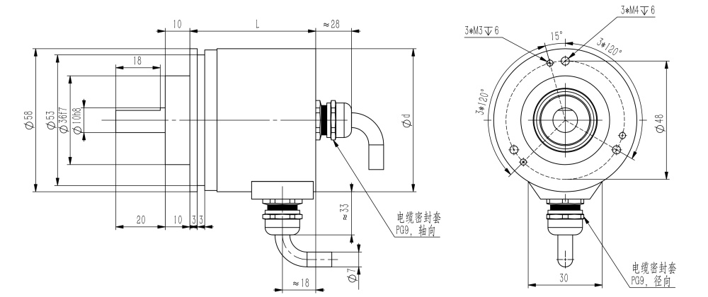
SAS/M58B
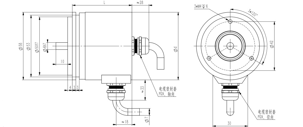
SAS/M58C
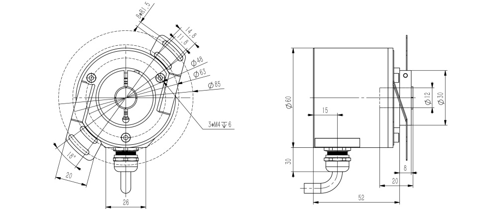
SAS/M58D
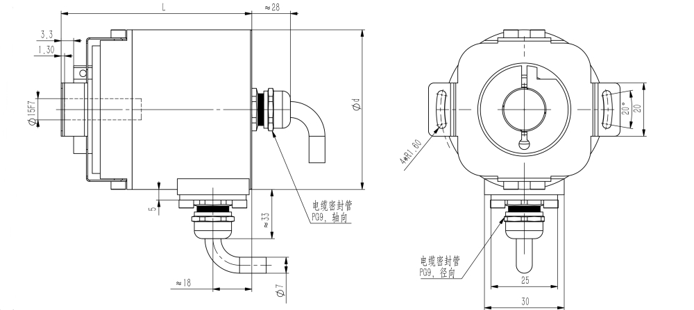
*Note: Axial lead-out = 42mm, radial lead-out L = 53mm.
*Aluminum housing: Diameter d = 59 mm; Stainless steel housing: Diameter d = 61 mm.
*Aluminum housing: Diameter d = 59 mm; Stainless steel housing: Diameter d = 61 mm.
Real-time Model Selection and Generation
| SA | ① | 58 | ② | - | ③ | ④ | ⑤ | - | ⑥ | - | ⑦ | ⑧ | ⑨ | - | ⑩ |
Note: For special shaft diameters, bore sizes, or cable lengths, please contact us for customization.
Sividi Encoder
TEL: +86 15050450799 (WeChat same number)


© Kunshan Sividi Co. Site Map Su ICP No. 14036688  Su Gong Network Security No. 32058302003763


